

I realized I didn't have a voltage regulator in my el co. After the battery dying from idling with the headlights on I figured I would take my alternator in to autozone and have it checked out. The have me the thumbs up so while I was there I bought a voltage regulator thinking this may be part of the problem for the battery not charging. So ultimately I'm working to solve the battery not staying charged while motor is running.
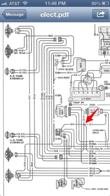
So first question: what does it mean when there is a dot on a wiring diagram and an inter section of multiple wires as pointed to with the arrow?
![Image]()
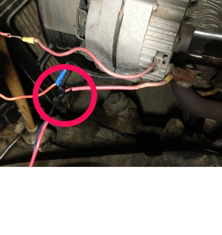
Next question/issue. I tried to use the wiring diagram and none of my wires match the diagram. So what I see is 3 wires coming off the alternator. 1 on the back going to the battery, and two more wires in a plug on side of the alternator. A black and red wire. I connected a wire (orange) to the black wire in the plug and ran it to the top position on voltage regulator. There is another wire I crimped in with the orange and that wire was previously connected to the black wire on the alternator so I didn't know if I should remove it or where that wire is going so I left it attached and added on a wire to the regulator. I connected the red wire from the alternator plug to the 2nd position on the regulator.
![Image]()
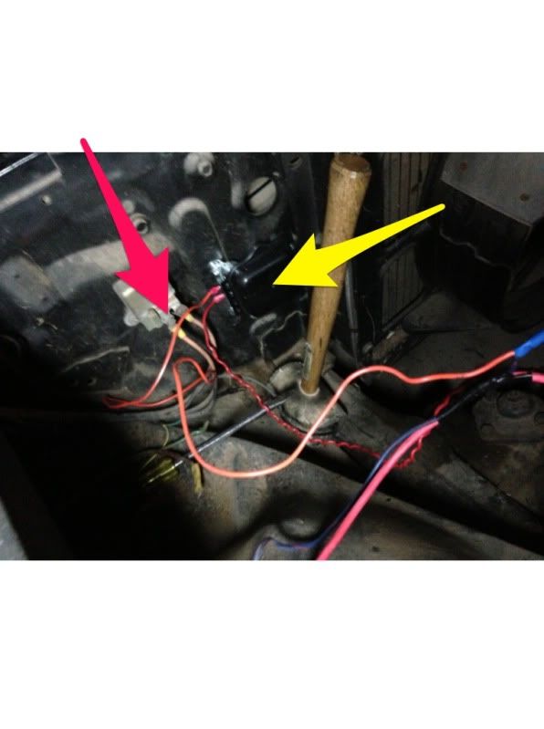
Yellow arrow points to new voltage regulator and the red arrow points to the horn relay. On the horn relay, I took a wire off the right side and added it to the left terminal post as that is how the diagram appeared. So the right terminal on horn relay goes from the alternator to the relay and the left terminal has one wire that goes to the battery and another wire that goes to ????
![Image]()
![Image]()
Does this look right? I just have the wires loose for a mock up to make sure the alternator is working in place. Can anyone help me
Figure out what's going on here?
Thank you,
So first question: what does it mean when there is a dot on a wiring diagram and an inter section of multiple wires as pointed to with the arrow?
Next question/issue. I tried to use the wiring diagram and none of my wires match the diagram. So what I see is 3 wires coming off the alternator. 1 on the back going to the battery, and two more wires in a plug on side of the alternator. A black and red wire. I connected a wire (orange) to the black wire in the plug and ran it to the top position on voltage regulator. There is another wire I crimped in with the orange and that wire was previously connected to the black wire on the alternator so I didn't know if I should remove it or where that wire is going so I left it attached and added on a wire to the regulator. I connected the red wire from the alternator plug to the 2nd position on the regulator.
Yellow arrow points to new voltage regulator and the red arrow points to the horn relay. On the horn relay, I took a wire off the right side and added it to the left terminal post as that is how the diagram appeared. So the right terminal on horn relay goes from the alternator to the relay and the left terminal has one wire that goes to the battery and another wire that goes to ????

Does this look right? I just have the wires loose for a mock up to make sure the alternator is working in place. Can anyone help me
Figure out what's going on here?
Thank you,


